


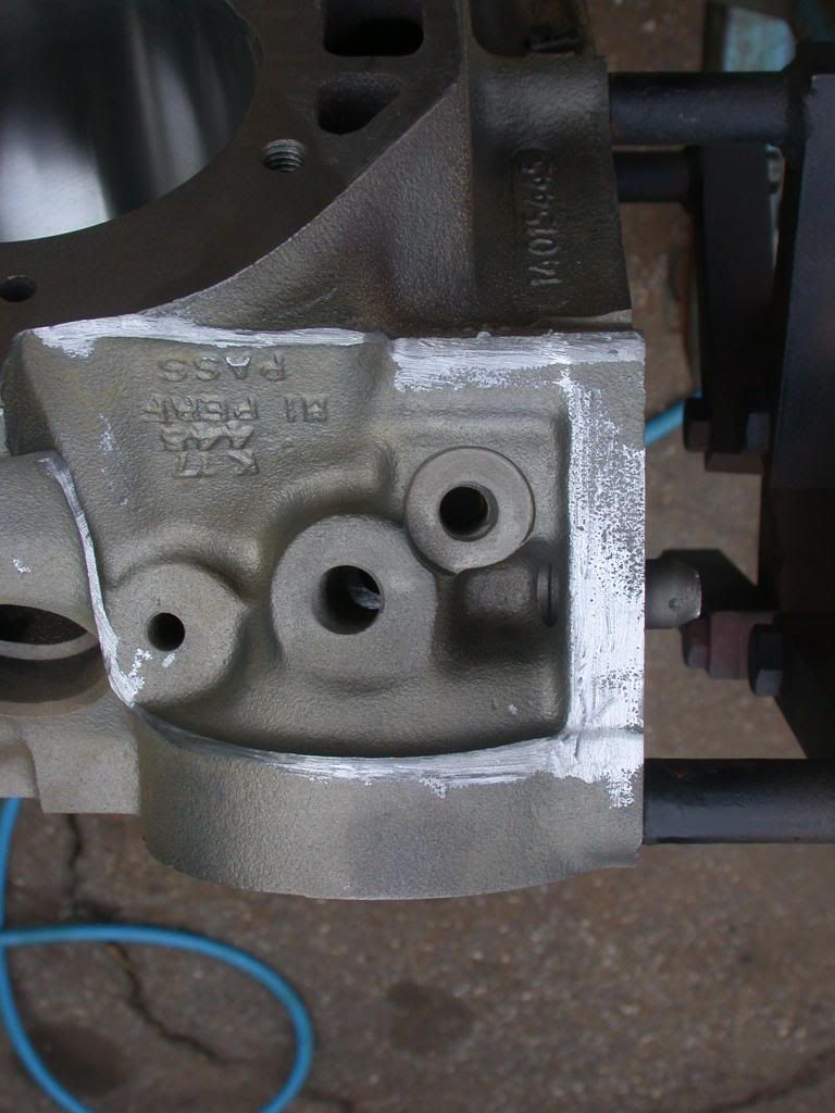
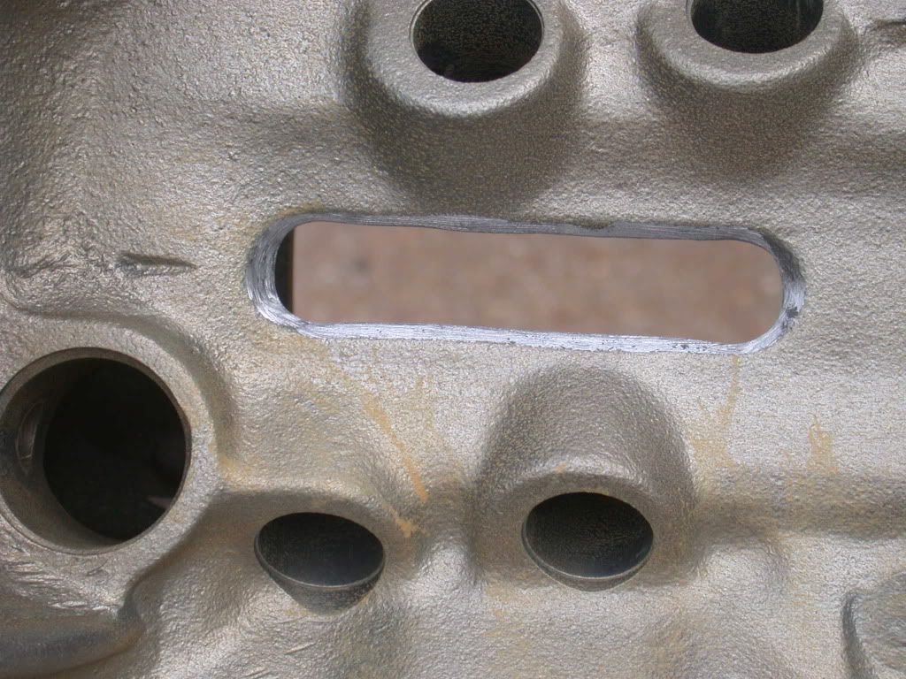
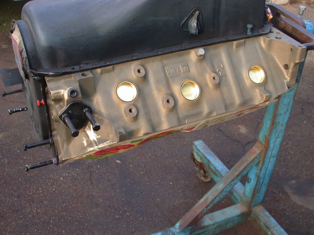
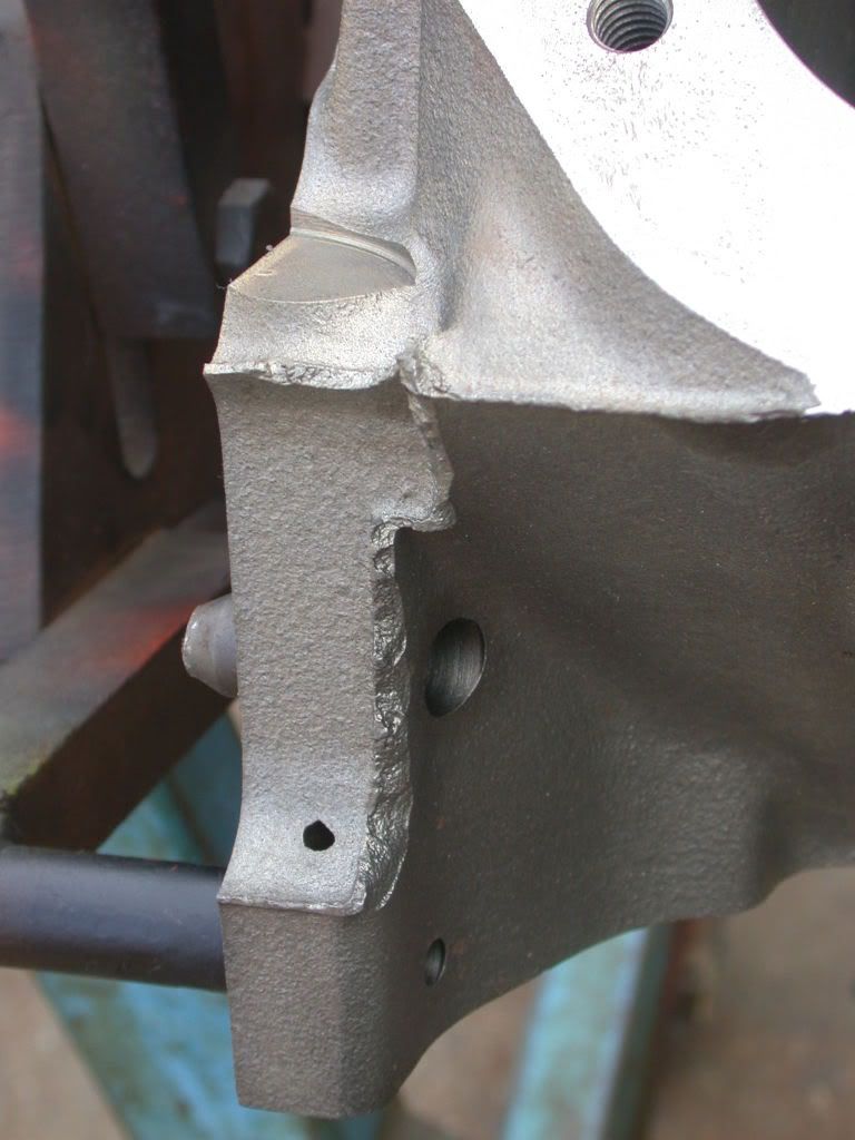
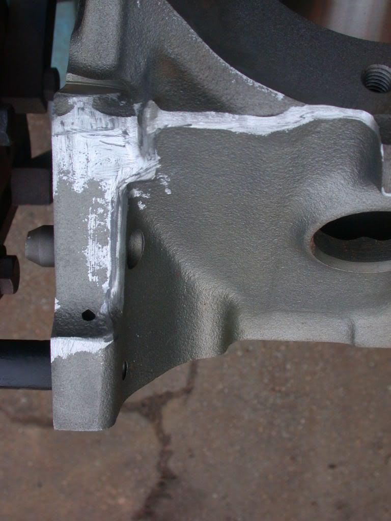
The block gets the standard "Obnoxious" deburr treatment, which is not only cosmetically pleasing, but also helps prevent the owner getting cut while cleaning the bilge in the boat. Before and after photos of several details on the block:
Results 1 to 10 of 37
Hybrid View
-
01-08-2013, 03:49 PM #1Senior Member

- Join Date
- Oct 2012
- Posts
- 377
-
01-08-2013, 03:50 PM #2Senior Member
- Join Date
- Oct 2012
- Posts
- 377
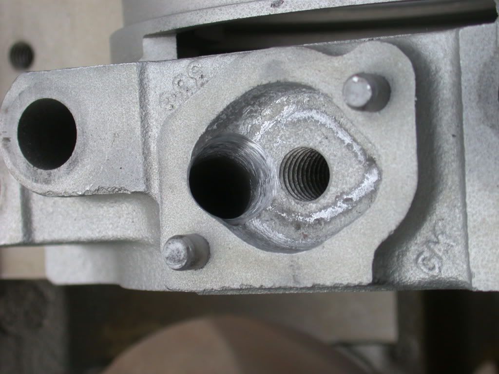
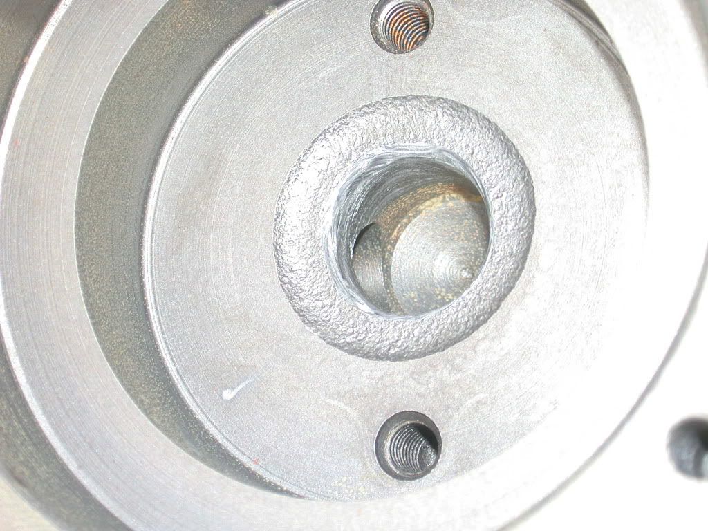
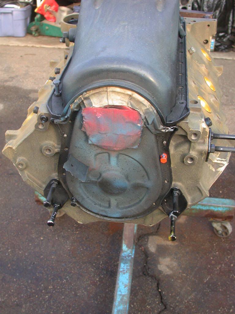
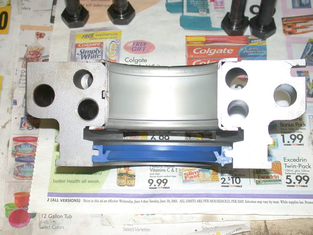
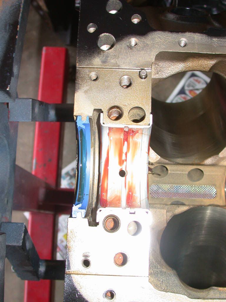
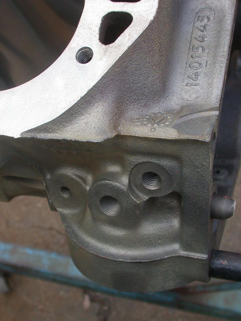
A few more "detail" photos, including rear main cap for smoother oil flow, and also the oil return to the block from the oil filter:
-
01-08-2013, 03:51 PM #3Senior Member
- Join Date
- Oct 2012
- Posts
- 377
I am not able to shoot photos during the block washing process with the degreaser and water flying all over, but I normally do a complete 3 step wash, solvent or degreaser with brushes and scrubbing,, high pressure water through all passages, then a soap and water wash, applied with a high pressure sprayer,, more brushes and scrubbing, another high pressure application of a more diluted soap and water mix,, and then finally all oil passages rinsed with a very high pressure nozzle on the hose, every direction it can be accessed from.
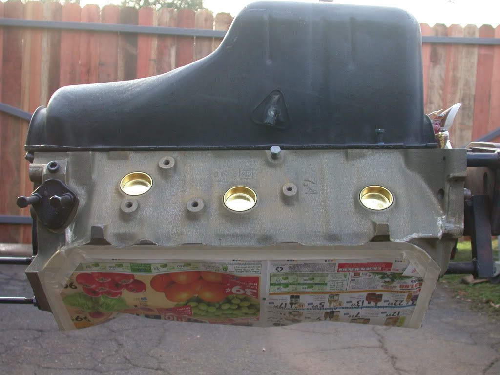
The cylinders get oiled down as soon as they are blown out, and the block is allowed to dry prior to masking for paint. I have dedicated oil pan, timing cover and pipe plugs so that I can do a neat job and not get overspray on gasket areas. I use masking tape and paper to cover the top, tracing the outline of the head gasket rather than just a straight line of tape.
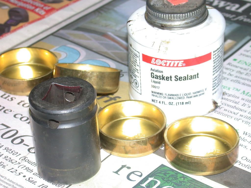
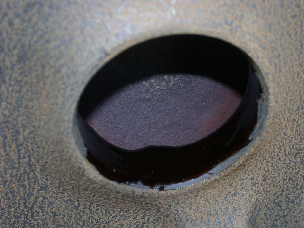
I also prefer to install the new brass freeze plugs prior to painting, since they won't stay shiny very long. I have always had excellent luck with Aviation grade Permatex(by Loctite now) brushed into the holes in the block carefully, so there won't be a bunch on the surface I want to paint.
-
01-08-2013, 03:52 PM #4Senior Member
- Join Date
- Oct 2012
- Posts
- 377
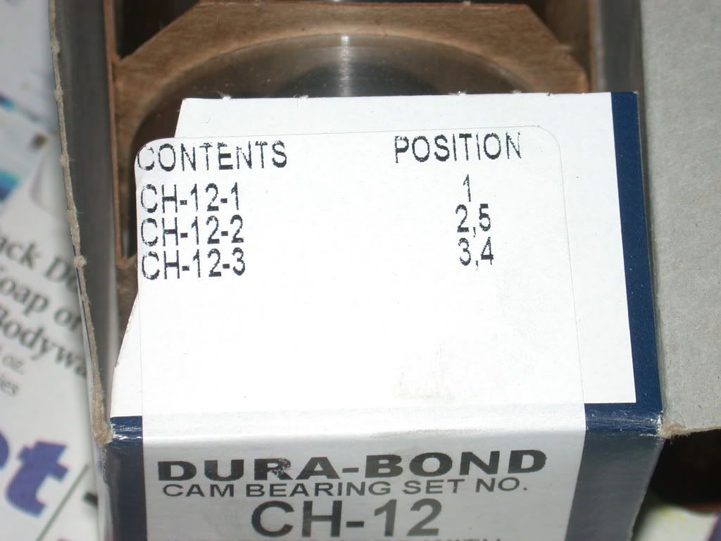
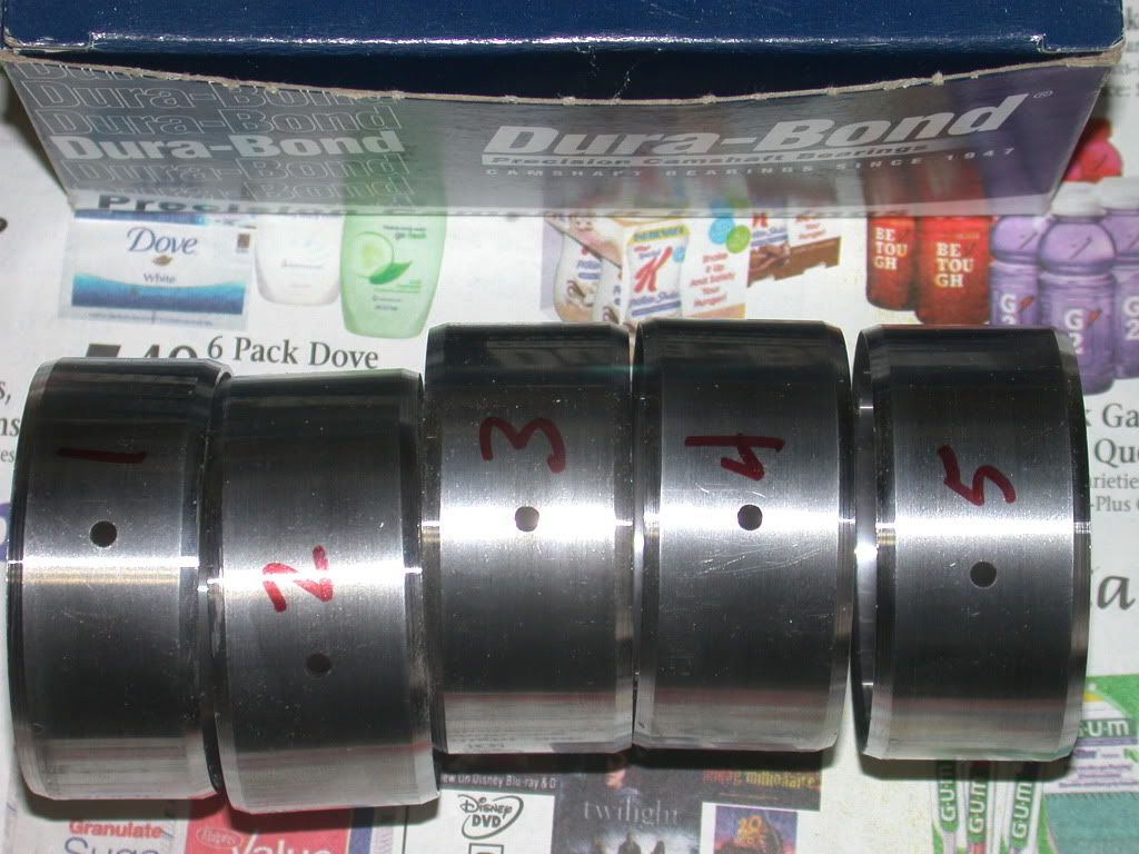
After the block is painted, I install the cam bearings. The box shows the positions the bearings need to go in, and to make it easy I use a felt pen to write the numbers on them near the oil hole that will need to be aligned with the oil hole from the main saddle. Durabond cam bearings are the accepted norm for most of my builds. When something works with no failures, why change?
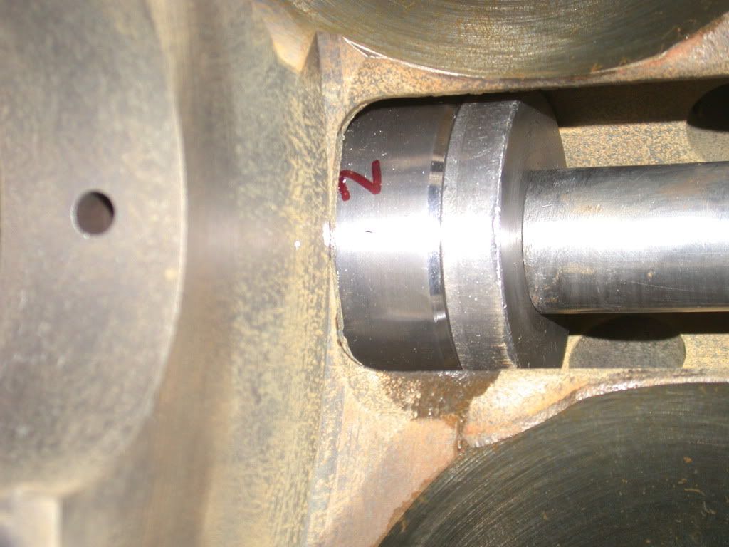
I think the glare obscures the oil hole in the bearing, but it gets carefully aligned with the oil passage in the block, so the cam bearing won't be starved for oil.
I put a piece of white paper towel inside the installed bearing so I could get a photograph showing the entire hole of the bearing is basically centered in the oil passage.

-
01-08-2013, 03:52 PM #5Senior Member
- Join Date
- Oct 2012
- Posts
- 377
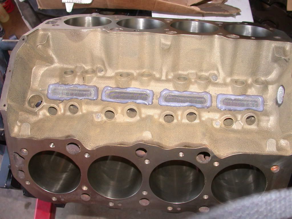
Then valley screens are epoxied into the valley since it's a roller cam engine, just in case there is a problem with a lifter tie bar or something, to help prevent debris getting into the bottom end and beating parts up.
-
01-08-2013, 03:53 PM #6Senior Member
- Join Date
- Oct 2012
- Posts
- 377
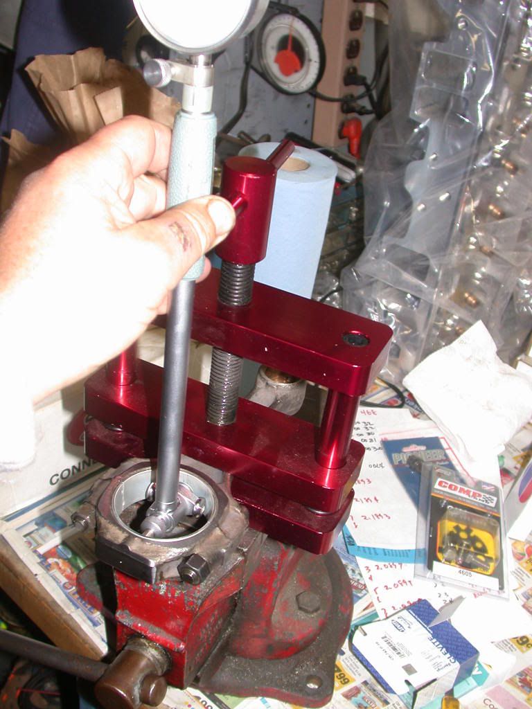
The crankshaft was measured, and bearing clearances determined by torquing bearings in place. I guess I didn't get photos of the mains being measured on this one, but here is one of the rods being checked with the dial bore gauge.
-
01-08-2013, 03:54 PM #7Senior Member
- Join Date
- Oct 2012
- Posts
- 377
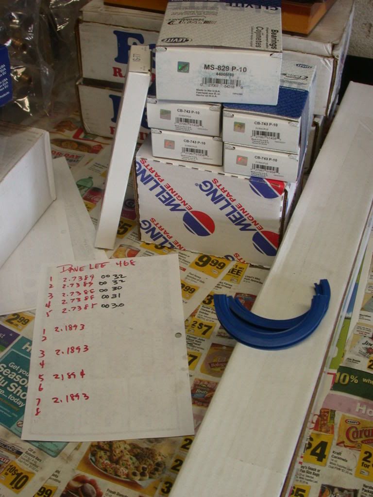
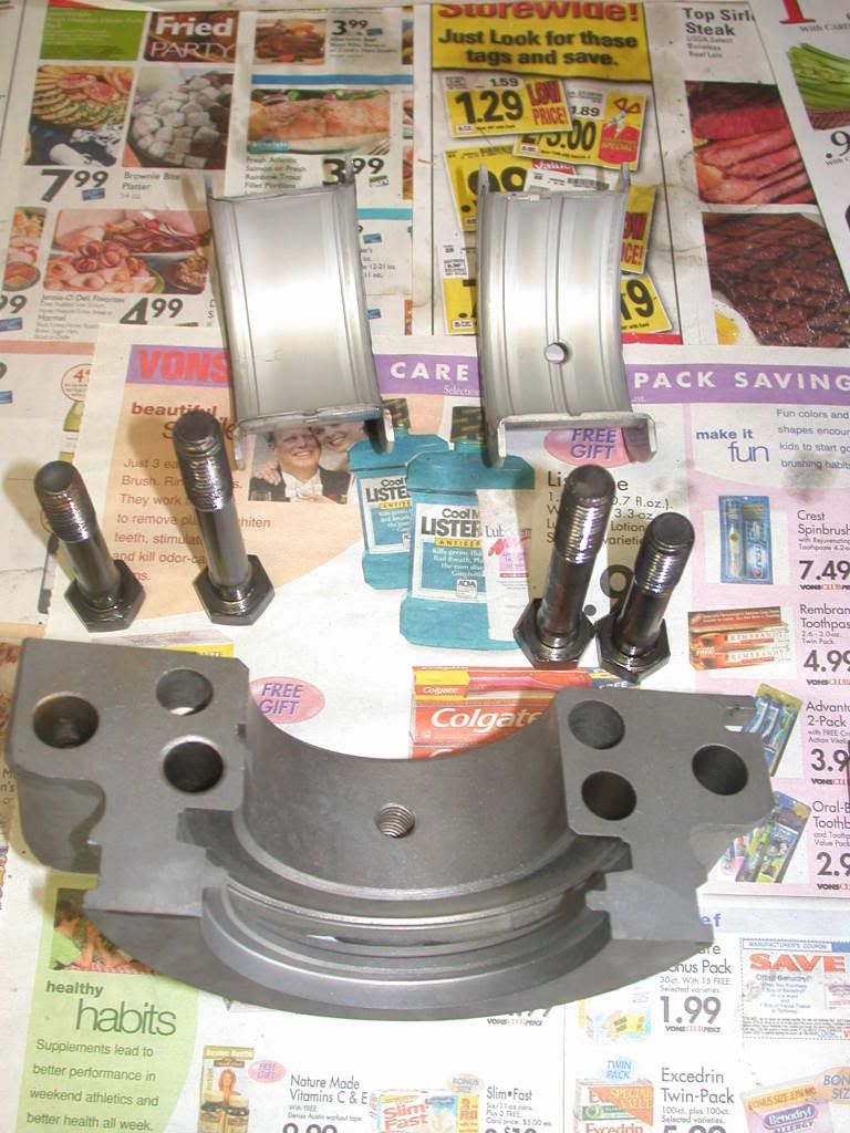
Some of the new parts waiting to go in the new engine, next to the notes on bearing measurement prior to adding the rod bearing clearances.
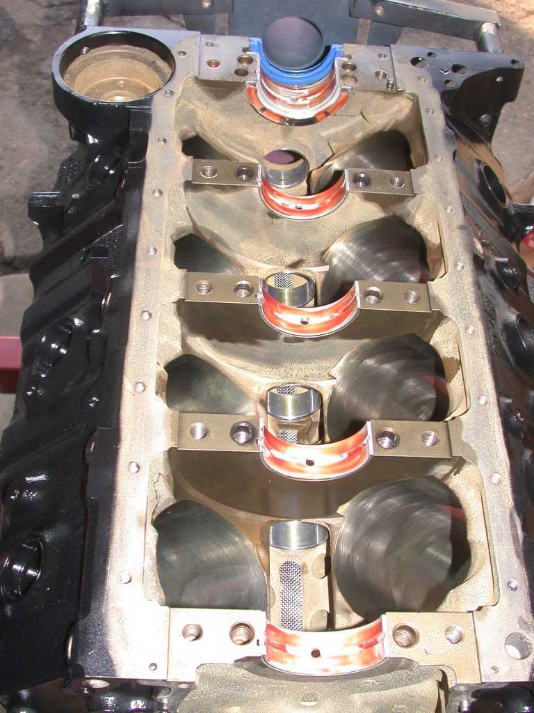
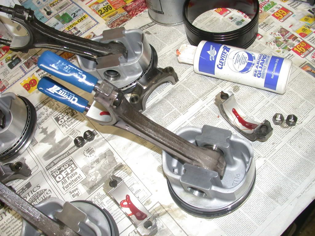
The "fitted" main bearings are set into the saddles and lubricated with a good quality assembly lube. Here I use Clevite bearing lube that gets carefully spread on the clean bearings. I also put a bit on the rear main seal after it has been "glued" to the block and rear main cap. Note also the correct direction of the lip of the rear main seal.
-
01-08-2013, 03:55 PM #8Senior Member
- Join Date
- Oct 2012
- Posts
- 377
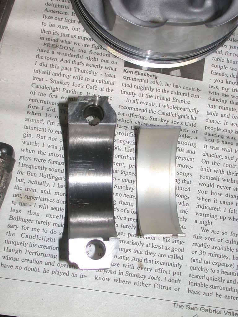
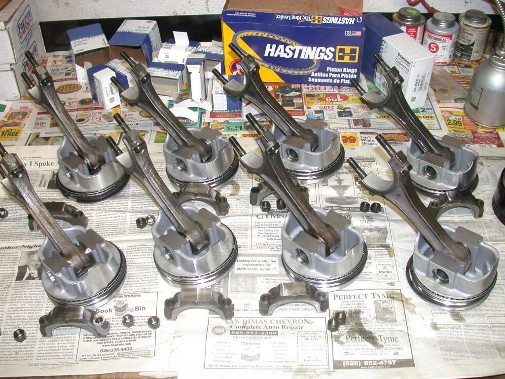
Here's a few shots showing the cleaned, assembled rods and pistons, and one of the rod cap showing the fresh hone marks from being resized. They also get the Clevite bearing lube. Main and rod bolts all get lubricated with oil prior to assemble, necessary to achieve proper torque specs. Note the blue rod bolt protectors, used to keep the rod bolts from nicking the crank.
-
01-08-2013, 03:55 PM #9Senior Member
- Join Date
- Oct 2012
- Posts
- 377
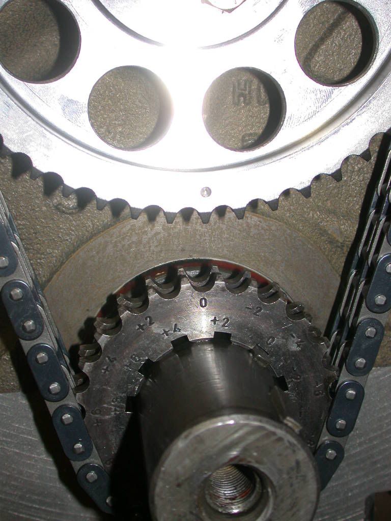
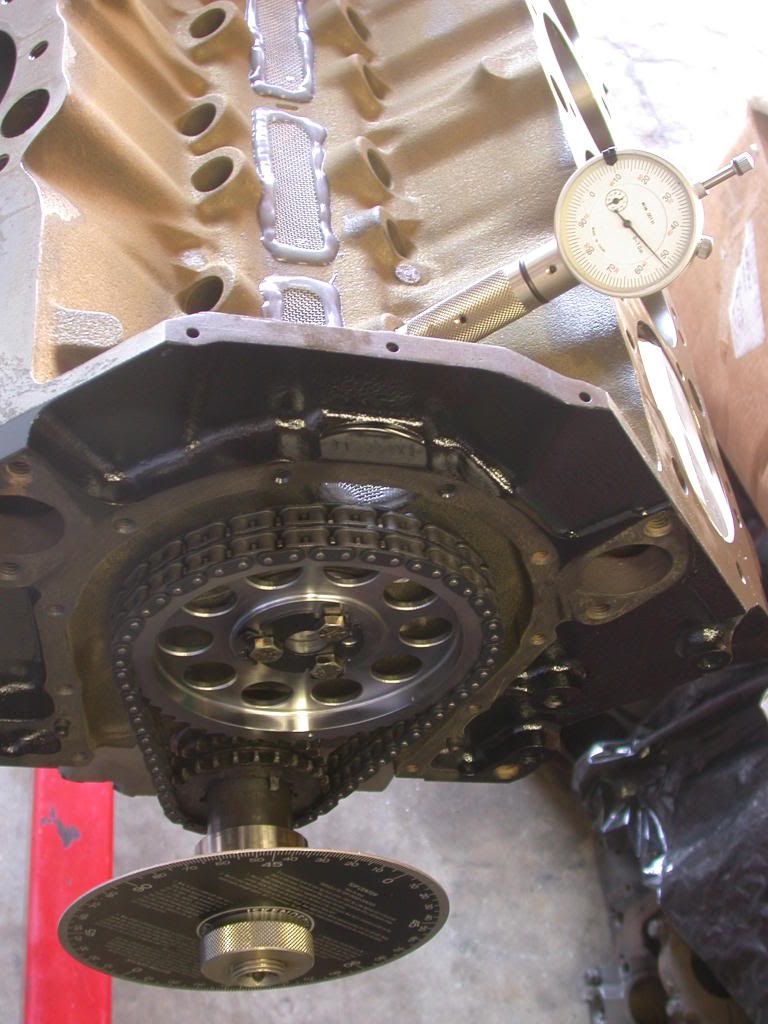
The camshaft installed, the double roller timing set is installed. Make sure the oil galley plugs are put into the block first, otherwise you might forget and have a huge internal oil leak. The camshaft is "degreed" or checked with a degree wheel to make sure it's installed as it was designed. In this instance, I had to use the 4 degree retard position(after the photo was taken, since it clearly shows it straight up, or at 0 degrees), and installed the 112 LC cam at 110.5, or 1 1/2 degrees advanced, primarily to counter the affect of the timing chain stretching.
-
01-08-2013, 03:56 PM #10Senior Member
- Join Date
- Oct 2012
- Posts
- 377
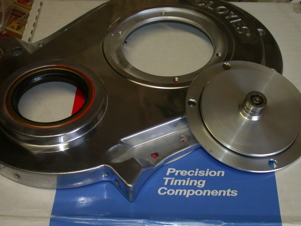
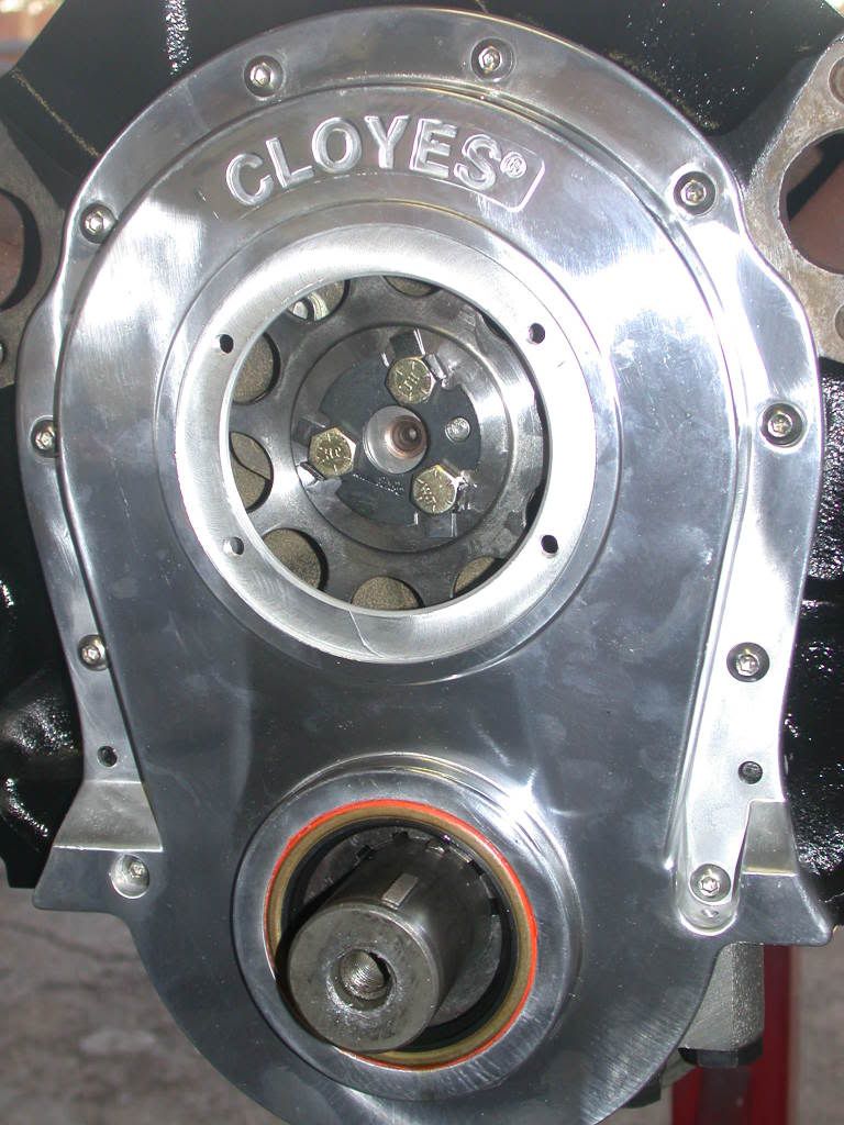
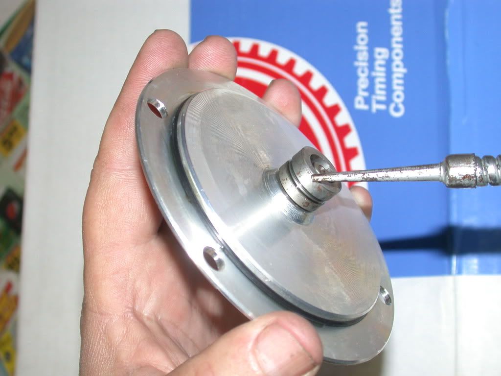
I have taken a strong liking to the Cloyes two piece timing covers, with the built in adjustable cam thrust adjustment. I think it's practically fool proof, and saves a bunch of time cutting down a thrust bumper for proper cam end play. The Cloyes cover does not include a front seal, so don't forget to buy one, and it should be carefully pressed into place. I use gasket cinch to help insure there are no leaks around the perimeter of the seal. I also care fully oil the thrust prior to bolting it onto the cover, and had previously oiled the thrust bearing behind the billet timing gear, as well as putting some oil on the chain and gears.

 Reply With Quote
Bookmarks